Understanding Induction Motors: Essential Guide for Mechanical Engineers
Introduction
Induction motors form the backbone of industrial machinery worldwide, powering equipment from compact ventilation systems to massive industrial pumps and conveyor belts. Their appeal lies in straightforward engineering, affordability, and exceptional durability under continuous operation. This practical guide breaks down induction motor fundamentals for engineers, focusing on design elements, operational mechanics, performance factors like slip and torque curves, and real-world uses—particularly relevant for pump system applications.
Fundamental Operation
At its core, an induction motor operates as an alternating current (AC) device where power feeds solely into the stationary outer component, called the stator. The inner rotating part, the rotor, gains energy through electromagnetic induction without any wired connection. This design ensures the rotor spins at a pace just below the stator's magnetic field rotation, earning it the alternate name "asynchronous motor." The critical speed gap, termed slip, drives current flow in the rotor to generate usable mechanical force.
Key Structural Components
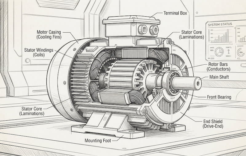
Every standard three-phase induction motor features two primary assemblies: the stator and rotor. The stator comprises layered magnetic steel sheets with grooves housing three sets of coils linked to a three-phase power source. These coils energise to produce a smoothly rotating magnetic influence across the narrow gap surrounding the rotor.
The rotor sits on a central shaft linked to the driven machine. Most prevalent is the squirrel-cage variant, featuring parallel conductive rods—typically aluminium—locked together by circular end caps, resembling a cage. This setup demands no upkeep as connections remain permanent. Alternatively, slip-ring rotors employ wound coils on the rotor linked to external rings on the shaft, enabling added resistance for startup boosts or velocity adjustments.
Generating the Rotating Field
Supplying balanced three-phase current to the stator coils yields a magnetic field that revolves steadily at a defined pace. This synchronous velocity derives from the formula: synchronous rpm equals 120 times supply frequency divided by pole pairs. For instance, a 50-hertz supply with four poles results in 1,500 revolutions per minute. This constant-speed field sweeps past the rotor, setting the stage for energy transfer.
Detailed Operational Sequence
Operation unfolds progressively. First, stator currents establish the revolving field at full synchronous speed. Initially stationary, rotor bars experience maximum relative motion as the field glides by. Faraday's electromagnetic induction principle then generates voltage and current loops within these bars or windings.
These rotor currents spawn a secondary magnetic field that aligns and clashes with the stator's, yielding rotational force propelling the rotor forward. Acceleration continues until equilibrium, where rotor pace lags sufficiently to perpetuate induction. Equilibrium prevents exact synchronisation, as matching speeds would halt relative motion, voltage generation, and torque output.
Role of Slip in Performance
Slip measures the percentage by which rotor speed trails synchronous speed, expressed as (synchronous minus rotor speed) over synchronous speed. At startup, slip hits 100 percent; under typical load, it settles at 2 to 5 percent for optimal efficiency. This minimal discrepancy maintains current induction without excessive energy loss.
Low slip yields torque roughly matching load demand linearly. Beyond a threshold, torque climbs to a peak—termed pull-out capacity—before declining toward stall conditions. Engineers rely on this profile to gauge overload tolerance and safeguard systems.
Analysing Torque-Speed Profiles
Torque-speed plots reveal motor behaviour across its range. Near full speed, the line slopes gently upward with slip, ideal for steady loads. Midway, curvature steepens toward maximum torque around 20 percent slip, providing overload margin. Past peak, torque plummets, signalling risk of halt under extreme demand.
This characteristic suits constant-speed tasks but permits brief surges. Negative slip enables generator mode, where the external drive exceeds synchronous speed, flipping power direction—useful in wind turbines or regenerative setups.
Classifying Induction Motors
Categorisation occurs by phase count or rotor style. Three-phase models excel in factories for self-starting reliability and broad power scalability. Single-phase versions suit domestic tools needing auxiliary startup aids like capacitors.
Among three-phase, squirrel-cage types claim over 90 percent market share for their maintenance-free robustness and cost-effectiveness, though startup torque limits apply. Slip-ring designs offer superior launch pull and velocity tuning via resistor banks, at higher complexity and cost.
Launch Techniques
Direct full-voltage startup works for modest sizes, tolerant of surge currents six to eight times rated. Larger units employ staged approaches: star-delta reconfiguration slashes initial current to one-third while delivering full torque post-transition. Auto-transformers or soft-starters further tame inrush electronically.
Slip-ring motors insert rotor resistors progressively, maximising startup force while curbing current. Modern inverters now dominate, ramping voltage and frequency for smooth acceleration and precise control.
Strengths and Constraints
Induction motors shine through brushless simplicity, slashing wear and service needs. They boast strong part-load performance, decent power factor, and resilience in dusty or moist settings with proper casing. Costs stay low across kilowatt to megawatt scales.
Drawbacks encompass moderate startup grip—addressed by specialised bar shapes—and inherent fixed speed absent drives. Light-load efficiency dips, and precise positioning demands extras like encoders. Variable frequency drives overcome most issues today, enabling throttle control via frequency tweaks while preserving torque.
Industrial Deployments
Versatility defines applications: pumps and blowers leverage affinity laws for flow-volume matching in water treatment or HVAC. Compressors drive steady pneumatic supply in manufacturing. Material movers like belts and hoists populate warehouses and mines.
Building services rely on them for chillers and exhausts. Even vehicles occasionally employ them where toughness trumps peak finesse. In pumping—your domain—their overload capacity and VFD pairing optimise variable demand, cutting energy in centrifugal stages.
Engineering Selection Criteria
Pick based on duty power, voltage class, frame size, insulation grade, and enclosure code against the environment. Full-load speed hints at slip and poles; efficiency and factor guide economics. Factor startup needs, inertia match, and service factor for peaks.
Ambient heat, altitude, and harmonics influence derating. Bearings warrant grease cycles or seals. Lifecycle hinges on right-sizing: oversize wastes power, undersize overheats. Pair with drives for pumps to trim throttling losses via speed dial.
Common Queries Answered
Why asynchronous? Rotor trails field perpetually for induction; synchronisation kills torque.
Zero slip outcome? No relative speed equals no currents, no drive motor coasting.
Squirrel-cage ubiquity? Cage simplicity yields unbeatable ruggedness and economy.
Conclusion
Mastering induction motors equips engineers to harness reliable power across sectors. Their blend of physics elegance and practical grit ensures enduring relevance, especially boosting pump efficiency through informed choices.