The seal is usually the victim
When a pump goes down, the seal is what leaked, so the seal gets replaced. If it fails again four months later, a better seal gets specified. When that one fails too, the conversation turns to the supplier.
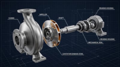
By that point everyone is looking in the wrong place. A mechanical seal is one of the most sensitive parts of a pump. It fails early and visibly when conditions are wrong, which makes it an excellent diagnostic instrument and a poor culprit. A seal that keeps failing is usually reporting a problem somewhere else.
What the faces actually need
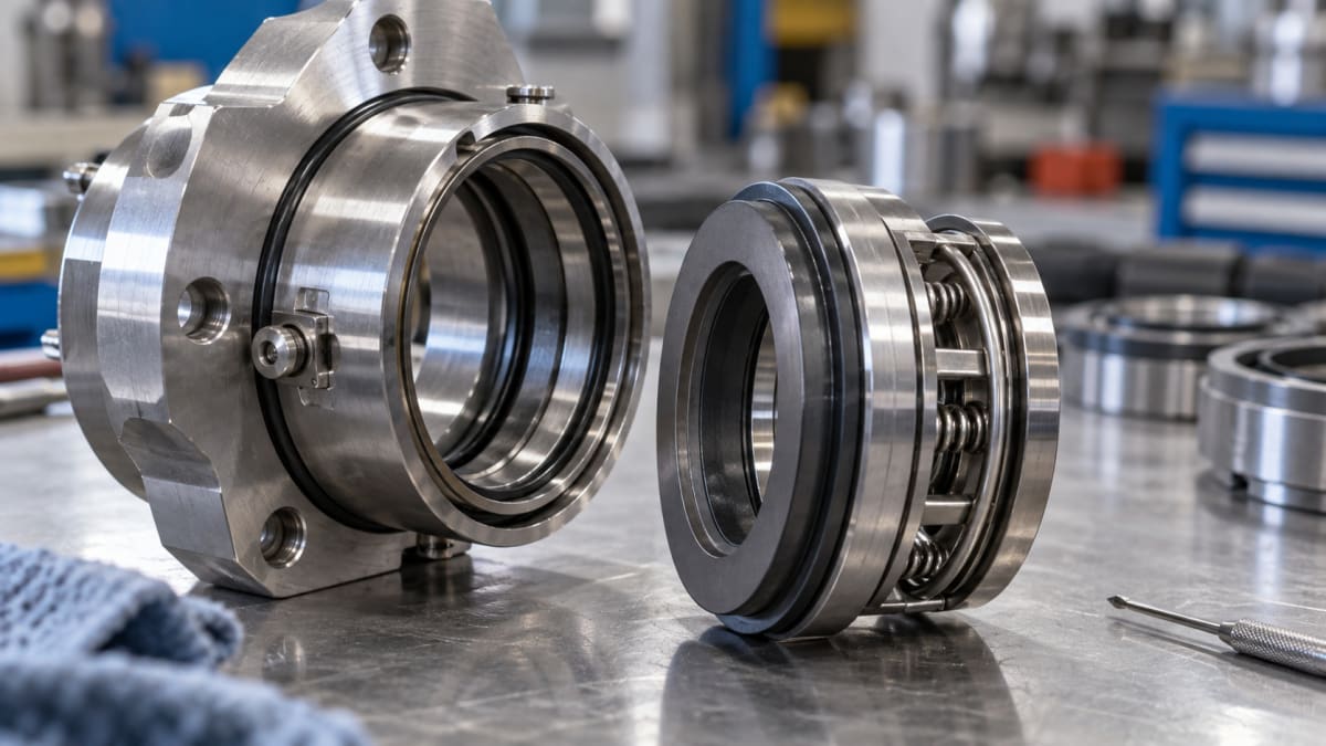
Strip away the springs, bellows and elastomers and a mechanical seal is two flat rings pressed together: one turning with the shaft, one fixed in the housing. They are lapped flat to within a fraction of a wavelength of light.
The critical thing is that they are not supposed to touch.
Between the faces sits a liquid film perhaps one micron thick, formed from the pumped fluid itself. That film does two jobs: it lubricates, and it carries away the heat generated by shearing. A seal running properly is hydrodynamically separated, and it will run for years.
Take the film away and the faces make contact. Contact generates heat, heat vaporises whatever liquid remains, and the loss of liquid causes more contact. That runaway takes seconds, not hours, which is why a seal can survive five years and then fail in an afternoon.
Almost every seal failure is a failure of that film. The useful question is never why did the seal fail, but what happened to the film.
The four things that actually kill seals
1. The film boiled, or was never there. Run a pump dry, even briefly, and the film is gone. The same outcome follows from a vapour-locked suction line, a closed suction valve, running against a closed discharge until the liquid heats, or a fluid close to its vapour pressure at seal-chamber conditions. Hot water and light hydrocarbons are unforgiving here, because a small pressure drop across the faces is enough to flash them.
2. The environment is wrong for the fluid. Solids in the pumped liquid get dragged between the faces and grind them. Fluids that crystallise on cooling, such as caustic and some brines, deposit solids as the film evaporates at the outer edge. Fluids that polymerise or coke at temperature do the same with hard deposits. In each case the seal is being asked to make its own lubricant out of something unsuitable.
3. The shaft is not where the seal thinks it is. Seals tolerate very little movement. Coupling misalignment, a soft foot, pipe strain pulling the casing out of position, worn bearings or shaft deflection from radial load all move the faces relative to each other. The faces then open and close once per revolution, and at 2,950 rpm that is fifty film interruptions every second.
4. The pump is running away from its best efficiency point. This one is under-appreciated and it connects everything above. Far to the left of BEP, internal recirculation begins, radial load rises sharply and the shaft deflects. Far to the right, NPSH available may fall below required and cavitation begins. Both put the faces in motion. A seal failing repeatedly on a pump running at 40% of BEP is not a seal problem, it is a selection or control problem. If you are unsure where your machine sits, our pump efficiency calculator will place it.
What a flush plan is really for
This is where API 682 comes in, the standard covering seals for centrifugal pumps in oil, gas and chemical service, and the origin of the piping plan numbers that appear on every seal datasheet.
A flush plan is not plumbing detail. It is the engineering answer to the question: how will this seal keep a liquid film? Each plan solves a different threat.
Plan 11 takes a small flow from the pump discharge, through an orifice, into the seal chamber. It raises pressure at the faces above vapour pressure and sweeps heat away. It is the default for clean, cool fluids, and it works because it is simple.
Plan 13 recirculates from the seal chamber back to suction instead, used on vertical pumps and wherever the chamber would otherwise trap vapour.
Plan 21 and Plan 23 add a cooler. Plan 21 cools discharge flow on its way in. Plan 23 is the better engineering: a small pumping ring circulates the same liquid in a closed loop through a cooler, so you cool a small trapped volume repeatedly rather than continuously cooling fresh hot product. On hot water and hot oil service, Plan 23 is usually the right answer and Plan 21 the expensive habit.
Plan 32 injects clean liquid from an external source. This is what you use when the pumped fluid is simply unfit to lubricate a seal: slurries, catalyst-laden streams, anything abrasive. It works, but you are now diluting your product, and the injection must never stop.
Plans 52 and 53 are for dual seals. Plan 52 holds an unpressurised buffer fluid between two seals: the inner seal does the work, the buffer contains any leakage, and rising level or pressure in the reservoir tells you the inner seal has started to go. Plan 53 pressurises the barrier fluid above product pressure, so any leakage is barrier fluid inward rather than product outward. For toxic or environmentally regulated services, Plan 53 is often not a choice.
Plan 62 puts a quench, usually steam or water, on the atmospheric side, washing away deposits that would otherwise build up and damage the faces from outside.
Choosing a plan is choosing which failure mode you are designing against. Fitting Plan 11 to a crystallising service is not a small mistake; it is the wrong answer to the question.
The faces will tell you what happened
A failed seal is evidence. Before it goes in the bin, look at it.
- Even, polished wear across both faces - normal life, and the seal did its job
- Heavy heat checking, radial cracks, discoloured faces - the film was lost; look for dry running, vapour, or a blocked flush line
- Scoring and embedded particles - solids reached the faces; the flush plan is wrong for this fluid
- Wear concentrated on one side, or an uneven band - the faces were not parallel; look at alignment, pipe strain and bearings
- Chipped outer edges - hydraulic instability, often from operating far off BEP
- Hard deposits on the atmospheric side - needs a quench, or one that is actually working
A short practical checklist
When a seal fails a second time on the same pump, stop replacing it and work through this instead.
- Where is the pump running relative to BEP? Measure, do not assume.
- Is the flush line actually flowing, and is the orifice clear?
- Is seal chamber pressure comfortably above the fluid's vapour pressure at temperature?
- Has alignment been checked cold and hot, and is there pipe strain on the casing?
- Is the flush plan right for what you are pumping today, rather than what the plant was designed for a decade ago?
Most repeat seal failures are answered somewhere in those five lines. The seal itself is nearly always the last thing wrong.